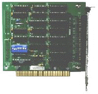
The NaTKiT1 Digital I/O Kit provides the hardware needed for NaTKiT1 to accept user input from micro switches. The kit consists of a 24 channel digital I/O board, an external 50 way screw terminal board and a 50 way ribbon cable to connect them. NaTKiT1 reserves 8 of the 24 channels for itself. In the future the remaining 16 channels will be available to the user though the current software issue does not support this. INSTALLATION First the I/O board has to be installed in the PC. Remember to observe anti-static precautions. Leave the mains lead from the PC plugged in to the wall socket but turn the wall socket off. The PC's case should now be at mains earth and touching the case will discharge any static from you before handling the I/O board. a) whip the cover off the PC, Now connect the terminal board to the I/O board using the ribbon cable. The connectors on the ribbon have a key way to ensure correct insertion. So you can test the installation connect a single pole, normally open switch, between terminals 1 and 2 on the terminal board. You could improvise a switch with two bits of wire. To test the board you now have to tell NaTKiT1 that the board is there. Run the programme select Engineer then System maintenance. The choice Dig I/O Address (Hex) should be showing Not there. Set the address to the I/O board's default 2C0 and then select the TEST below Dig I/O Address (Hex). Applying a short circuit between pins 1 and 2 should now make the character T appear briefly. A short circuit between pins 3 and 4 should make RETURN appear briefly. INPUTS You are now ready to connect your micro switches and go! Please note that if the switch is connected to 1 and 2 it can only initiate a test sequence. If the unit fails or, there are operator decision tests or any other situation that requires input other than T the operator will have to input from the keyboard or mouse. If the switch is connected to 3 and 4, ie returning a carriage return, then the default at each operator decision will be selected. This could lead to confusing results. OUTPUTS The level between terminals 9 and 10 will be high when a test sequence or a calibration is executing, or the Engineer facilities have been entered. The level is low at all other times. A test sequence is "in progress" from when the operator initiates the sequence and a pass or fail decision finally made. If the Operator Fail Check is active and a unit fails then the sequence is considered still in progress until either a pass is obtained or the operator replies N to the "Retest this unit" prompt. The level between terminals 11 and 12 will be high when the FAIL prompt is visible and low at all other times. If the Operator Fail Check is not active then this fail flag will always be valid. If the Operator Fail Check is active then the fail flag will only be valid when the Test in progress flag is low. GROUND All the even numbered terminals are commoned and at ground. |
|

