INTRODUCTION
 The NK OSwitch is for use with the NaTKiT loudspeaker production test systems. It is used to switch the associated amplifier’s output terminals or the input to the amplifier. The NK OSwitch is for use with the NaTKiT loudspeaker production test systems. It is used to switch the associated amplifier’s output terminals or the input to the amplifier. When output switching the test unit's input terminals are available to other test equipment when the NaTKiT system is not actively testing a unit. This might be used to impedance test the unit. When input switching the amplifier's input is available to other equipment when the NaTKiT system is not actively testing a unit. This might be used to make some specific distortion measurement. For the O Switch to operate the NaTKiT's PC must contain a Digital I/O Kit which are no longer available. SWITCHING OPERATION
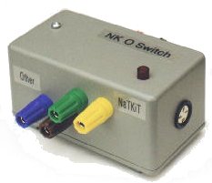
In the O Switch's "normal" condition, ie unconnected or the NaTKiT inactive, then the TEST UNIT terminals are connected to OTHER. If the NaTKiT is executing a test sequence, calibrating, or the Engineer facilities have been entered then the TEST UNIT terminals are connected to NaTKiT. GENERAL INSTALLATION First ensure that the NaTKiT's PC has a functioning Digital I/O Kit installed. If installing a Digital I/O Kit please see Digital I/O User Guide. Connect the locking 3 pin DIN plug lead supplied with O Switch to the DIN socket on the O Switch. At the other end of the lead connect to the 50 Way terminal connector supplied with the I/O Kit: the BLUE lead to terminal 9,
the GREEN and YELLOW lead to terminal 10, and
the BROWN lead to terminal 49.
OUTPUT SWITCHING INSTALLATION 
Connect the NaTKiT power amp output to the YELLOW and GREEN 4mm sockets (positive to YELLOW).
Connect a test unit to the RED and BLACK 4mm sockets (positive to RED).
Connect your "other" test equipment, eg an ohm meter, to the BROWN and BLUE 4mm sockets (positive to BROWN).
INPUT SWITCHING INSTALLATION 
Connect the NaTKiT power amp input to the RED and BLACK 4mm sockets (earth to BLACK).
Connect the NaTKiT’s output (phono plug) to the YELLOW and GREEN 4mm sockets (earth to GREEN).
Connect your "other" test equipment, eg an ohm meter, to the BROWN and BLUE 4mm sockets (earth to BLUE).
The block diagram shows optional splitting of the mike signal using a NaTCH mike splitter. |